Types,
Materials, Uses, and Technical Specifications
From powering up your device to transmitting data at lightning speed, electronic and optical cables are the silent workhorses of the modern world. Often overlooked, they play a crucial role in everything from industrial automation to consumer electronics, telecommunications, automotive, and robotics.
But not all cables are created equal.
Their internal structure, material composition, transmission medium (electrical or optical), and even physical dimensions can significantly influence performance, reliability, and cost.
In this comprehensive guide, we break down the different types of electronic and fiber optic cables, their characteristics, materials, and specific uses. Whether you’re selecting a cable for data transmission, RF signals, power delivery, or long-distance optical communication, this article will help you make the right choice.
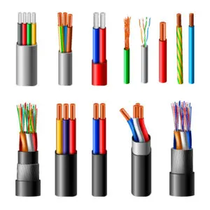
Understanding the main differences between electronic cables, made of different types of metal, and optical fiber, made of glass or plastic.
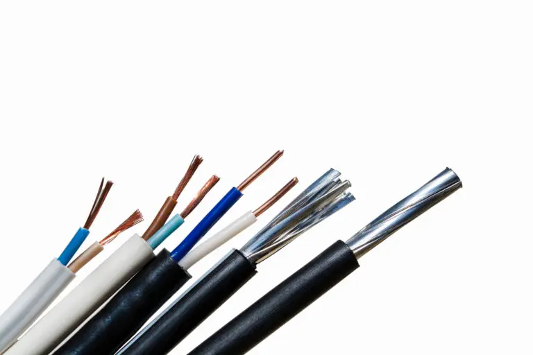
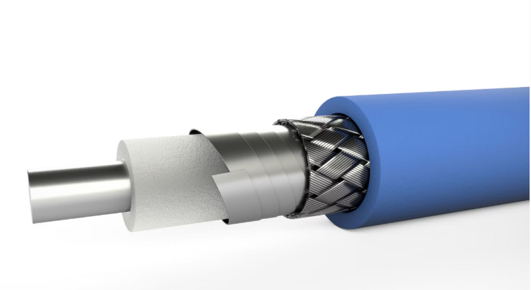
Electronic cable
It’s a conductor (or group of conductors) encased in insulating materials, designed to carry electrical energy or signals.
Electronic cable includes: • Conductor: Usually copper or aluminum, solid or stranded. • Insulation: A dielectric material surrounding the conductor (e.g., PVC, PTFE, Teflon). • Shielding: Optional protective layer (foil or braided) against electromagnetic interference (EMI). • Jacket: The outer layer that resists mechanical, thermal, or chemical stresses.
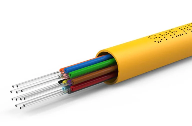
Fiber optic cable
Fiber optic cable transmits data using light pulses through strands of glass or plastic fiber.
Fiber optic cables include: • Core: The glass or plastic fiber where light travels. • Cladding: A reflective layer around the core. • Buffer/Strength Members: Protection and tensile strength. • Outer Jacket: Environmental protection.
Key cable characteristics
Conductor
Usually copper or aluminum (solid or stranded).
Insulation
Dielectric layer around the conductor, like PVC, PTFE, or Teflon.
Critical for data & RF (50Ω, 75Ω, 100Ω are common).
Voltage rating
Defines max working voltage.
Current capacity
Based on conductor size and insulation temperature rating.
Flexibility
Depends on conductor type and jacket material.
Cable size
Usually specified in AWG (American Wire Gauge).
Cable Comparison Table
Cable Type
Transmission
Max Data Rate
EMI Resistance
Max Distance
Flexibility
Cost
Coaxial
Electrical
~10 Gbps
High
~500 m
Medium
$$
Twisted Pair (UTP)
Electrical
10 Gbps (Cat6)
Medium
100 m
High
$
Ribbon
Electrical
Low (Kbps–Mbps)
Low
<1 m
High
$
Multi-Conductor
Electrical
Variable
Medium
Medium
Medium
$$
Power Cable
Electrical
N/A
Low
Short
Low
$$
Hook-Up Wire
Electrical
Low (DC/analog)
Low
Short
Very High
$$$
Shielded Cable
Electrical
Moderate
Very High
Medium
Medium
$$$
RF/Microwave
Electrical
>20 GHz
Very High
Medium
Low
$$$$
Data Cables (USB…)
Electrical
10–40 Gbps
Medium
1–5 m
Medium
$–$$$
Fiber Optic (MMF)
Optical
1–10 Gbps
Immune
2 km
Medium
$$$$
Fiber Optic (SMF)
Optical
Up to 100 Gbps+
Immune
10–100 km
Low
$$$$
Physical and Electrical Considerations
AWG (Wire Gauge): Lower AWG = thicker wire → more current, less resistance
Voltage Drop: Longer copper cables need thicker gauges to minimize loss
Attenuation: Fiber wins over distance; copper cables lose signal strength faster
Shielding: Required in EMI-heavy environments (industrial, automotive, RF)
Temperature Ratings: Silicone and PTFE insulations handle high heat
Types of electronic cables
From data transmission to power delivery, each cable type is engineered for specific applications, environments, and technical demands. The following overview breaks down the most common cable categories, highlighting their structure, features, advantages, and limitations to help you make informed choices across a wide range of use cases.
Structure: Two or more insulated conductors twisted together Types: Shielded (STP), Unshielded (UTP) Applications: Ethernet, telephony, audio, CAN bus Features:
Differential signaling
Reduced crosstalk
Impedance: typically 100Ω
Advantages:
Good noise immunity (especially STP)
Low cost
Flexible and lightweight
Limitations:
Limited frequency range
Distance limitations at high speeds
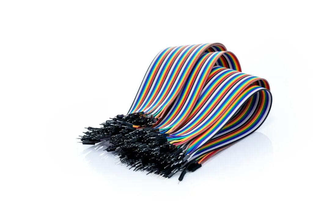
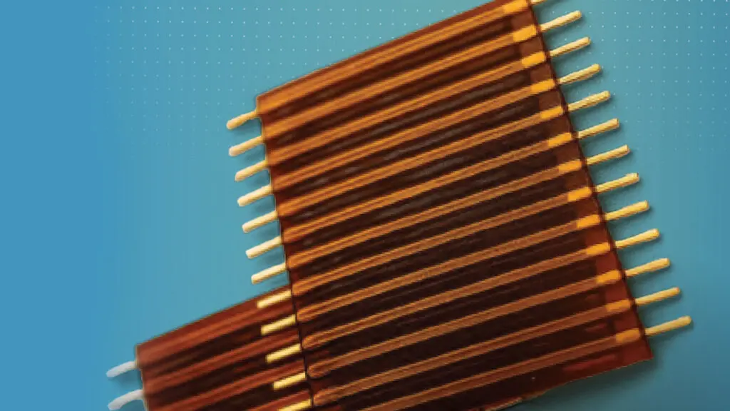
3. Ribbon Cables (Flat Cables)
Structure: Multiple parallel conductors in a flat, flexible layout Applications: Internal PC wiring, IDE/SCSI cables, printers Features:
Compact, flat profile
Up to 64 conductors
Pitch defines conductor spacing
Advantages:
Easy routing in tight spaces
Lightweight
Limitations:
Poor EMI resistance
Low current handling
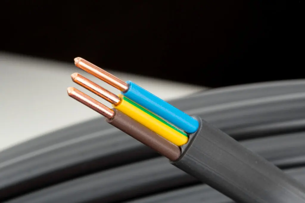
4. Multi-Conductor Cables
Structure: Several insulated conductors under a common jacket Applications: Control systems, industrial automation, sensors Features:
Often shielded
Variety of AWG sizes
Color-coded insulation
Advantages:
Streamlined wiring
EMI shielding possible
Limitations:
Bulkier
Harder to terminate
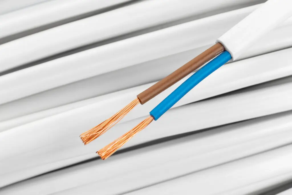
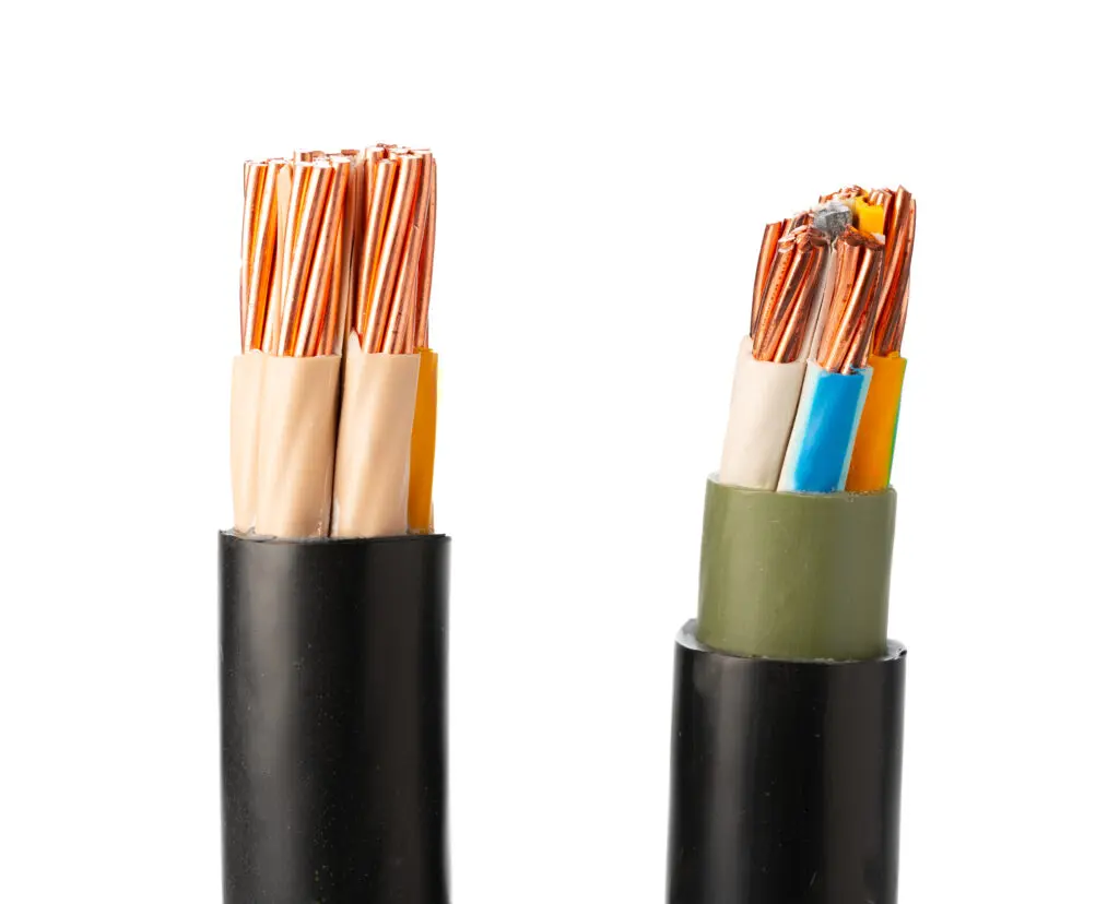
5. Power Cables
Structure: Thick copper/aluminum conductors + high-durability insulation Applications: AC power, batteries, power supplies Features:
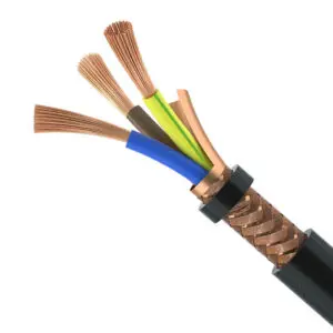
Structure: Any cable with foil/braid shield around conductors Applications: Audio, instrumentation, sensitive data transmission Features:
Foil or braided shielding
Drain wire for grounding
Advantages:
EMI protection
Better signal quality
Limitations:
More expensive
Bulkier and less flexible
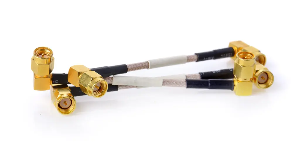
8. RF/Microwave Cables
Structure: High-precision coaxial with special dielectric and shielding Applications: RF test benches, antennas, GPS, radar Features:
Low-loss dielectric (PTFE, PE)
Very tight impedance tolerance
High shielding effectiveness
Advantages:
Minimal signal loss at GHz frequencies
Excellent phase stability
Limitations:
Expensive
Sensitive to bending
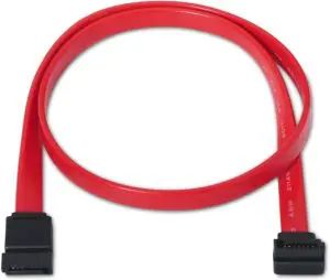
9. Data Cables (USB, HDMI, SATA, etc.)
Structure: Often twisted pair + shielding + specific pinout Applications: Computers, phones, AV, peripherals Features:
High-speed differential pairs
EMI shielding
Precise impedance (USB = 90Ω diff, HDMI = 100Ω)
Advantages:
High bandwidth
Plug-and-play data interfaces
Limitations:
Short length limits (e.g., USB ~5m)
Compatibility issues
Physical Dimensions and Standards
AWG (Wire Gauge)
Diameter (mm)
Typical Use
24–28 AWG
0.32–0.20 mm
Data, USB, Ethernet
18–22 AWG
1.02–0.64 mm
Signal, low power, control
10–16 AWG
2.59–1.29 mm
High current, DC power
<10 AWG
>2.59 mm
Battery cables, power feeders
Length considerations:
Data cables degrade over distance (USB max ~5m without booster).
Power cables lose voltage over length (depends on AWG & current).
RF cables suffer from attenuation; low-loss variants like LMR recommended.
Material Comparison
Material
Conductivity
Flexibility
Cost
Use Cases
Copper
Excellent
Good
$$
General-purpose, high current
Tinned Copper
Very Good
Good
$$
Marine, corrosive environments
Aluminum
Medium
Rigid
$
Power lines, low-cost
Silver
Excellent
Moderate
$$$$
RF, military, aerospace
Insulation Types:
PVC: Inexpensive, general-purpose
PTFE (Teflon): High-temp, chemical resistant
Silicone: Flexible, high-temp, low friction
Polyethylene: Low-loss dielectric (RF)
Common Use-Case Scenarios
Use Case
Recommended Cable Type
DC power delivery
14–18 AWG stranded copper
Audio systems
Shielded twisted pair
Ethernet networking
Cat 5e/6 UTP or STP
RF antenna
50Ω coaxial (RG-58, LMR-400)
High-speed USB
Shielded twisted pair, 90Ω diff
Industrial sensors
Shielded multi-conductor
Inside PC wiring
Ribbon or hook-up wire
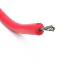
Robotics arms
Silicone flexible cables
Conclusion
Choosing the right electronic cable depends on your signal type, electrical specs, and environmental needs. Whether you’re wiring a power supply, building a robot, or designing an RF front-end, understanding cable types, materials, impedance, shielding, and size ensures performance and reliability.
Frequently Asked Questions About Electronic Cables
What makes a cable expensive?
Several factors drive up the cost of a cable:
Conductor quality: Pure, high conductivity copper (vs. copper clad aluminum), silver plating, or Litz wire raise the price.
Precision manufacturing: Cables with tightly controlled impedance (e.g. 50 Ω, 100 Ω), low-loss dielectric materials like PTFE, and tight dimensional tolerances require more complex production.
Shielding quality: Multiple layers of foil + braid shielding or drain wires add cost but improve EMI protection.
Jacket and insulation materials: PTFE, high temperature silicone, or flame retardant OFNR jackets cost more than standard PVC.
Certifications: Industry standards (e.g., TIA 568 for Ethernet, UL, RoHS) add testing and documentation expenses
What’s the difference between a cheap cable and an expensive one for the same use?
Signal integrity: Expensive cables maintain impedance, reduce insertion loss, crosstalk, and return loss .
Durability: Premium insulation resists heat, UV, moisture, and flex fatigue, offering longer life.
EMI shielding: High-end cables have better foil/braid shielding; cheaper ones rely on minimal or no shielding and leak more interference.
Manufacturing consistency: Premium brands have tighter specs and testing, while budget cables may vary even within the same model, affecting performance unpredictability.
Why does cable length matter?
Attenuation: Every meter reduces signal strength—more so at higher frequencies .
Voltage drop: In power cables, resistance over long lengths lowers voltage at the endpoint
Impedance mismatches: Over long runs, reflections can occur when cable length approaches a significant fraction of the signal wavelength (e.g., > λ/10)
Ethernet limits: Exceeding the standard 100 m Cat5e/6 limit can degrade bandwidth, introduce latency, and cause dropouts
Audio applications: Long speaker wires increase resistance; if wire resistance exceeds 5% of speaker impedance, sound quality may suffer
Does cable length affect network performance?
Yes:
Attenuation increases with length, reducing signal amplitude and bit error rate tolerance
Signal reflection risk increases if impedance isn’t consistent
Standards exist for a reason: e.g., Ethernet’s max recommended length is 100 m to avoid errors .
Are expensive audio cables really worth it?
World reviews agree: for most consumer setups, there’s no audible difference between cheap and high-end speaker cables — as long as conductor gauge and wiring quality meet specs
Exception: Extremely long runs or poor shielding may introduce measurable noise—shielded or thicker cables may be valuable then.
What is skin effect and does it matter?
Definition: High frequencies travel near the surface of the conductor, raising AC resistance.
Impact: Significant in RF cables or very long high-tension lines; for audio (≤20 kHz) and short lengths, skin effect is negligible
When it matters: In microwave/RF use, or thousands of meters long runs, cable design (like Litz wire) helps counteract skin effect.
Why is impedance control so important?
Returns signals: Mismatched impedance causes echoes, signal loss, degraded data – especially in high-speed digital and RF cables.
Industry standards define exact values: e.g., Ethernet (100 Ω), USB (90 Ω), RF (50/75 Ω)
At what point does cable length actually matter?
Data communications: Once length exceeds specs (e.g., 100 m for Cat6), you’ll see speed drops or errors
Speaker cables: For 8 Ω systems, 18 AWG cable is fine up to ~15 m; beyond that, resistance causes 5% loss
RF systems: Every meter counts, especially at GHz frequencies—use low-loss cable or amplifiers for long runs
Power runs: Copper wire resistance causes voltage drop; larger AWG is needed for long runs.
Are fiber optics better than copper cables? For high-speed, long-distance, and EMI-sensitive applications, yes. Fiber offers greater bandwidth, immunity to interference, and better security — but at higher cost and complexity.
Can fiber cables be used for power? No. Fiber only transmits light (data), not electrical energy.
FAQ Summary
Question
Short Answer
Expensive vs Cheap cable
Better material, shielding, consistency, durability, and performance specs
Length affecting performance
Causes attenuation, voltage drop, impedance mismatches, EMI leakage
Audio cable length
Matters only for very long runs; use thicker gauge
Network cable length
Watch max 100 m standard; longer cables degrade data quality
Do high-end audio cables help?
Not in short runs—just stick to correct gauge and decent build
Is skin effect a concern?
Only at high frequencies or extreme lengths
Why impedance matters?
Ensures clean signal transmission in digital/RF applications